C-13X: My First Handwired Keyboard
Published:
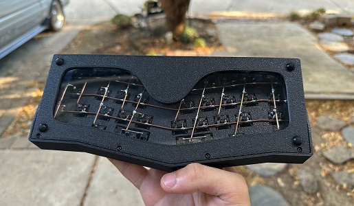 I’m an autodidact person. From improving my violin skills to learning digital animation and rigging, I enjoy teaching myself new skills. This summer I decided to handwire a custom mechanical keyboard. I originally planned to build a Dactyl-ManuForm but chose the C-13X since this is my first time handwiring and also because I enjoy typing on the alice layout. This was a fitting project to gain some experience with hardware and learn skills such as soldering.
Breakdown of parts I used | Total: ~$145
| Quantity | Part | Price |
|---|---|---|
| 1x | 3D Printed Plate + Top and Bottom Case | Quoted by u/srut2000 at r/3Dprintmything for $21.00 |
| 35x | Boba U4 Switches | $6.50 per 10 |
| 35x | 1N4148 Diodes | $5.99 per 100 |
| 1x | Elite-C Controller | $17.99 |
| 1x | Bare Copper 16g Wire (63 ft) | $19.95 |
| 1x | Stranded Tinned Copper Wire (I reccommend solid core instead) | $17.98 |
| 6x | D65 Gaskets | $5.00 |
| 8x | M2x6mm Screws | $8.49 per 100 |
| 2x | 2u Plate Mount Stabilizers | $1.50 each |
| 4x | 8mm Diameter Bumpons/Feet | $1.00 per 4 |
| 1x | Clear Plastic/Acryllic Sheet | $9.95 |
Tools I used | Total ~$215
| Product | Price |
|---|---|
| TS101 Soldering Iron B2 Kit | $76.99 |
| TS101 D24-Tip (optional) | $15.98 |
| 63-37 Tin Lead Rosin Core Solder | $8.99 |
| Coiled Brass Soldering Iron Tip Cleaner | $8.98 |
| Tip Tinner | $6.35 |
| Rosin Paste Flux | $7.49 |
| Solder Sucker | $22.95 |
| Wire Flush Cutter | $7.96 |
| Nylon Pliers | $11.99 |
| Plastic Sheet Cutter | $10.69 |
| Silicone Solder Mat (optional) | $18.89 |
| Helping Hands (optional) | $23.99 |
Building Process
Research time: 1.5 hours | Build time: 8-10 hours
Stabilizers and Plate Problem
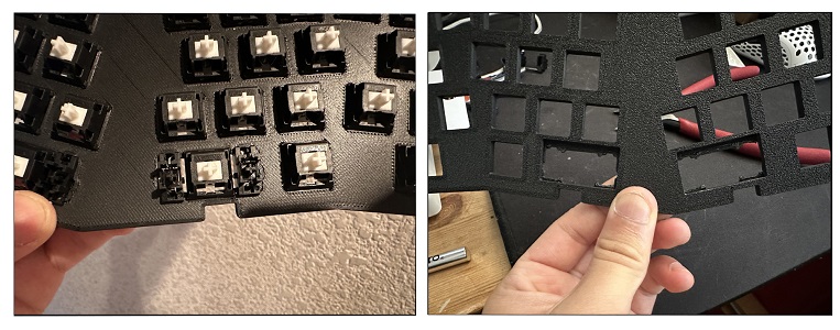 Before I even began handwriting the switches, I encountered spacing issues involving the stabilizers and the plate. The stabilizers were not aligning properly with the switches upon insertion, leading to the keycap jamming when pressed. I reached out to Flurples himself for assistance, but unfortunately, his suggestions did not fix the issue. To solve this problem, I modified the plate by trimming it slightly. This adjustment granted the switches and stabilizers a bit of free movement, enabling them to align seamlessly with a keycap attached. A visual comparison of the initial state (left side) and the modified state (right side) is depicted in the second picture.
Diodes and Matrix Wiring
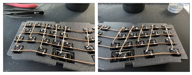 While handwiring for the first time, soldering the diodes was relatively manageable. I initially began by positioning the diode wire alongside the switch pin and then applying solder. However, I soon discovered that a more effective approach involved coiling the diode wire around the pin first to secure it.
Dealing with the copper wire, however, presented a challenge. With only a pair of nylon pliers and my bare hands, I manipulated the shape of the copper wire to follow the curve of the plate, inspired by Flurples’s design due to its visually appealing aesthetics. Assembling the rows posed slight difficulty due to the switches guiding the alignment.
Securing the columns required a helping hand device to maintain their position. Furthermore, connecting the middle switches to the column wire using short, bent copper wires proved to be quite laborious. The wires were prone to movement during the soldering process, even with a helping hand to hold them. Lastly, I would be lying if I said I did not burn myself a few times when soldering the matrix wiring.
Controller Wiring
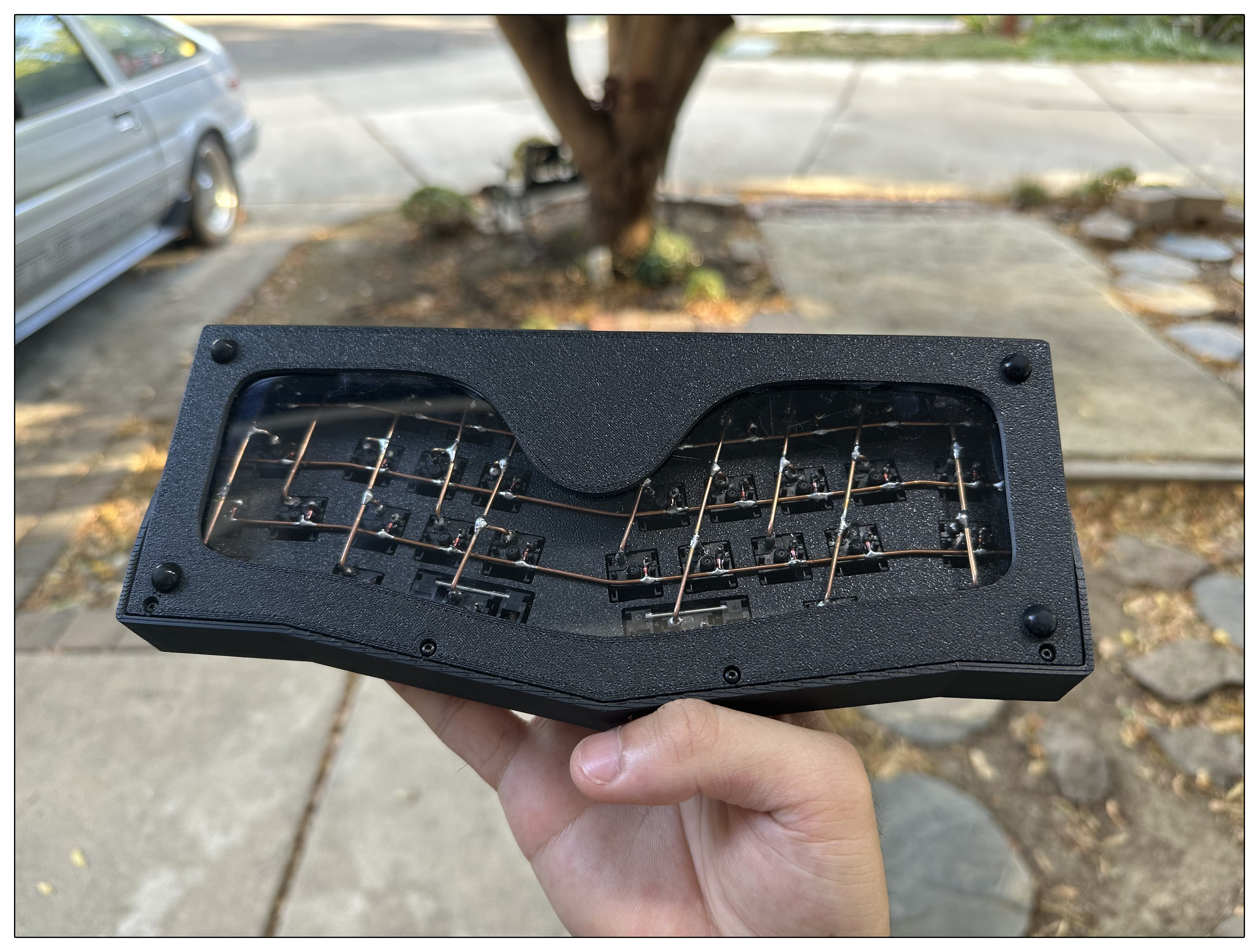
 After completing the matrix wiring, wiring the controller was straightforward. The process involved melting the existing solder, inserting the wire, and allowing it to cool and solidify, thus establishing a secure connection to both the switches and copper wires. Because I followed Flurples’s matrix wiring, I ensured to follow the wiring diagram so it would be compatible with the provided firmware.
Upon completing the controller wiring, I proceeded to flash the firmware using QMK Toolbox, followed by editing the layout with VIA. Fortunately, all the components worked flawlessly during testing. You can find the details of my customized keyboard layout below (outdated).  One aspect to take into account is the choice of using solid-core wire rather than stranded wire. The stranded wire I utilized needed to be twisted to retain its shape. However, there were instances during soldering when the wire became fragile, requiring me to restart.
Polycarbonate Plastic Window
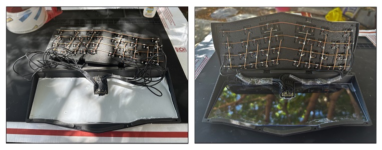 Carving the polycarbonate plastic into a shape compatible with the bottom case was a painstaking process. I started by measuring the case’s dimensions, cutting a corresponding piece of paper, attaching the paper onto the plastic sheet, and then meticulously scoring the sheet multiple times until it could be cleanly snapped off. I ended up creating two windows, as the first attempt was ruined by unintended cuts and fingerprints. This explains why the cover remains intact in the left photo, only to be removed soonly in the right photo.
Furthermore, I taped and superglued the controller wires to minimize their visibility when examining the case from below. If I could go back in time, I would definitely make the controller wiring shorter.
All that was left now was to screw the top and bottom case together.
End Result
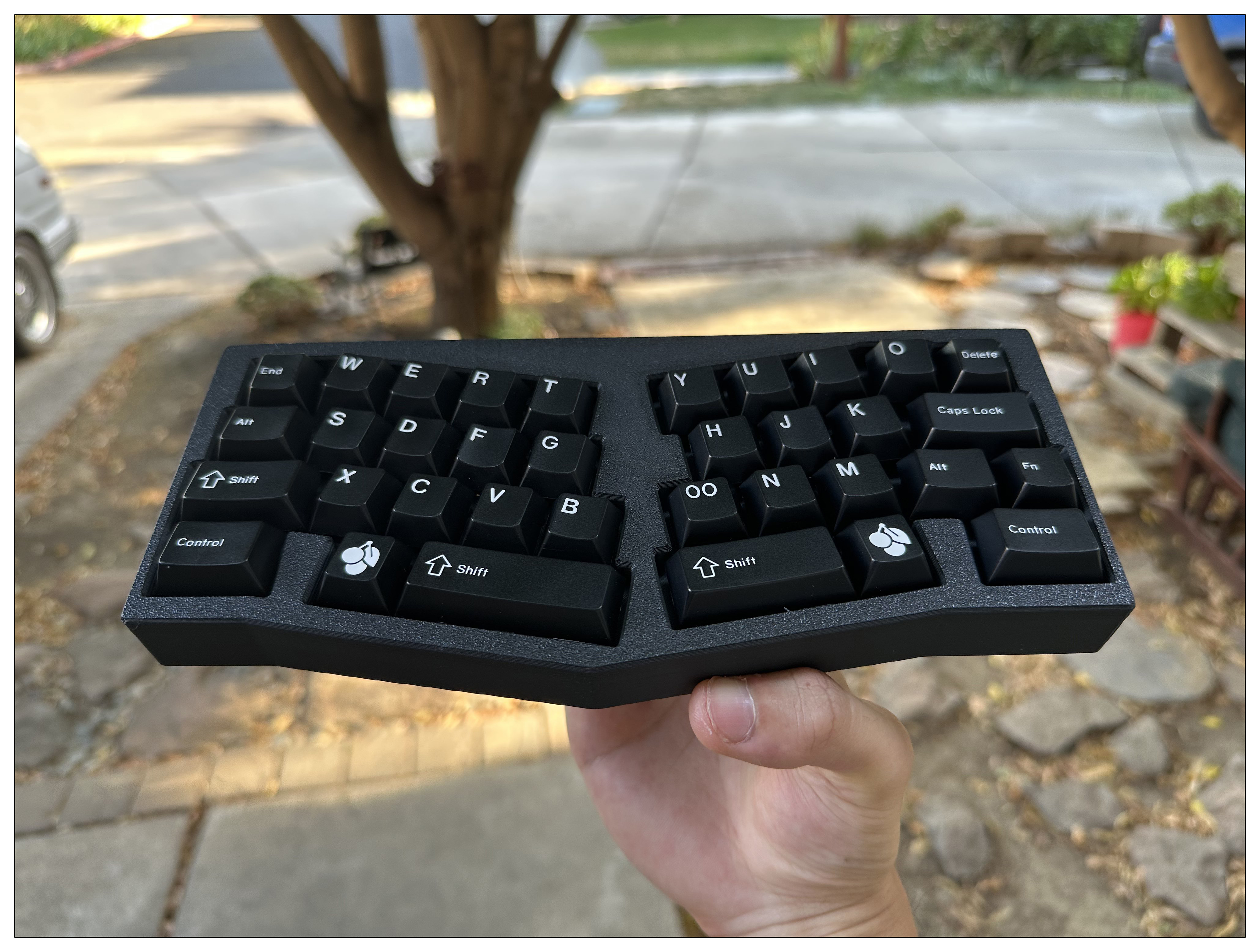
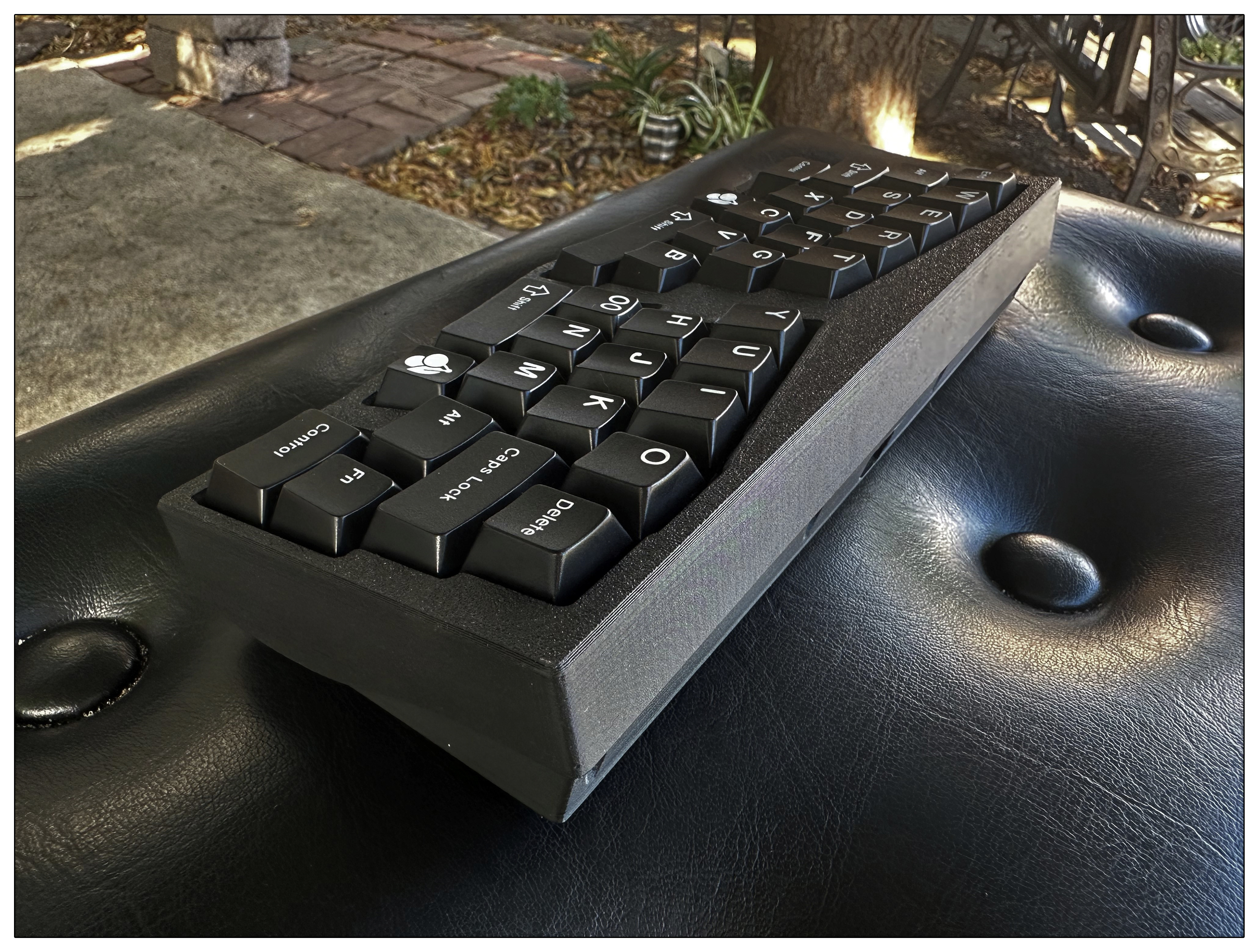
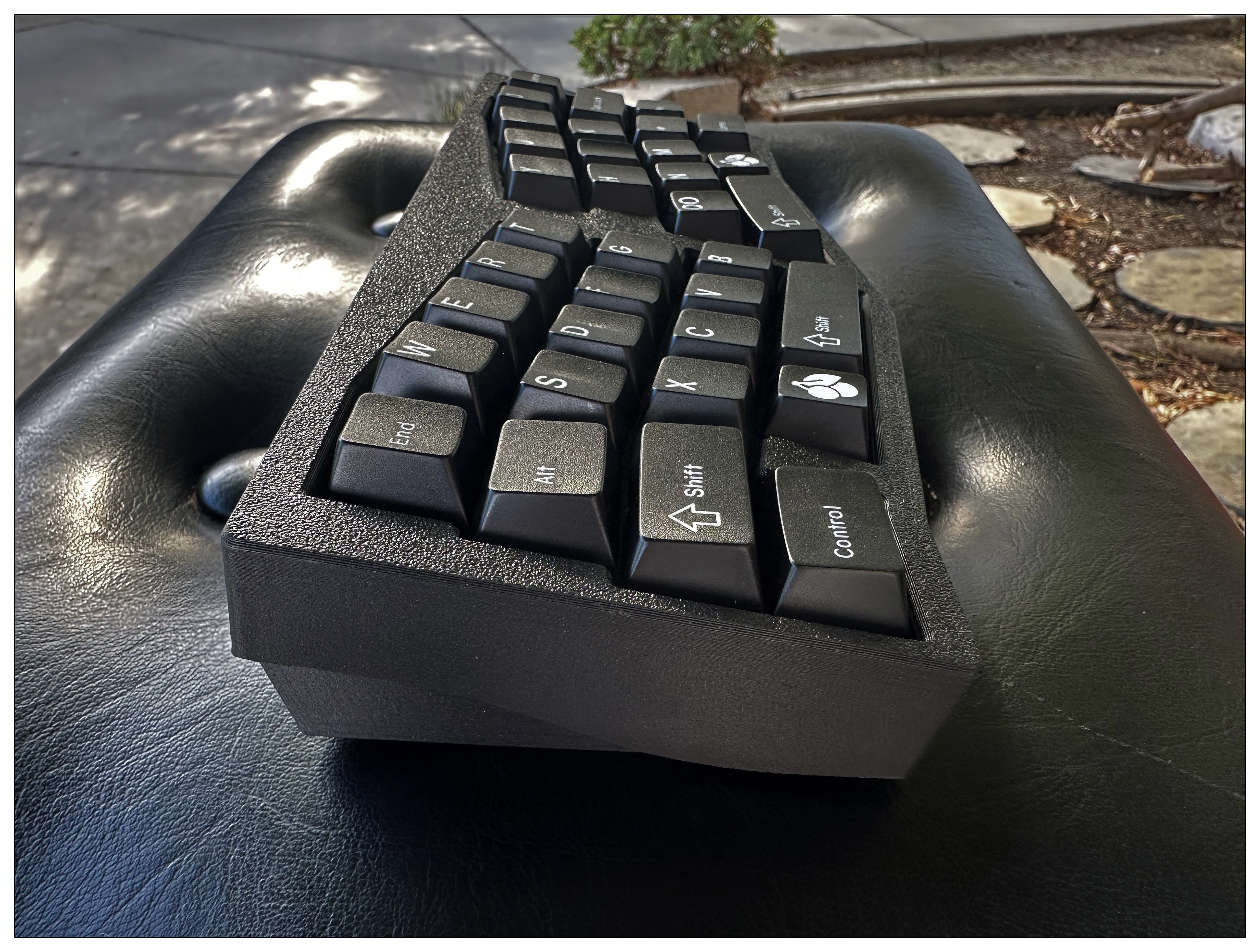
Reflection
The process of creating my first hand wired keyboard tested me on problem solving and experimenting. Starting from the initial issues of properly aligning the stabilizers with the plate, to wiring the diodes and matrix, each step in the process taught me how important it is to adapt and think creatively.
Soldering, which used to feel quite intimidating, gradually became something I could handle through handling different materials and most importantly, trial and error. Working with copper wire and trying to make it aesthetically appealing improved my craftsmanship and patience. Moreover, carving the polycarbonate plastic required a lot of precision and careful calculations. I have come to realize how technical skill and craftsmanship come together in a project like this.
This whole experience has helped me expand my technical abilities and strengthened my ability to problem solve. It was incredibly satisfying to finally see my hard work pay off when I successfully loaded the firmware and tested all the components. All the challenges I faced contributed to enhancing my skills and made achieving the final result even more rewarding.
In the future, I have plans to undertake more complex projects, such as constructing a Dactyl Manuform keyboard. Additionally, I aspire to delve into the realm of PCB design and create custom keyboard cases using 3D modeling software.
Resources
- https://github.com/flurples/C-13X, thank you Flurples for answering my emails and the open-source keyboard
- r/3Dprintmything, thank you u/srut2000 for printing and answering my questions regarding 3D printing
- How to Build a Handwired Keyboard - Joe Scotto
- How to Improve Your Handwired Keyboards - Joe Scotto
- Handwiring Discord, thank you regicidal.plutophage for helping me troubleshoot

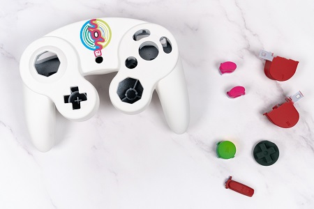 My brother is graduating this year and with his birthday coming up and his passion for competitive Super Smash Bros, I decided to create a custom GameCube controller as a gift. Modding a GameCube controller can’t be that difficult… right?